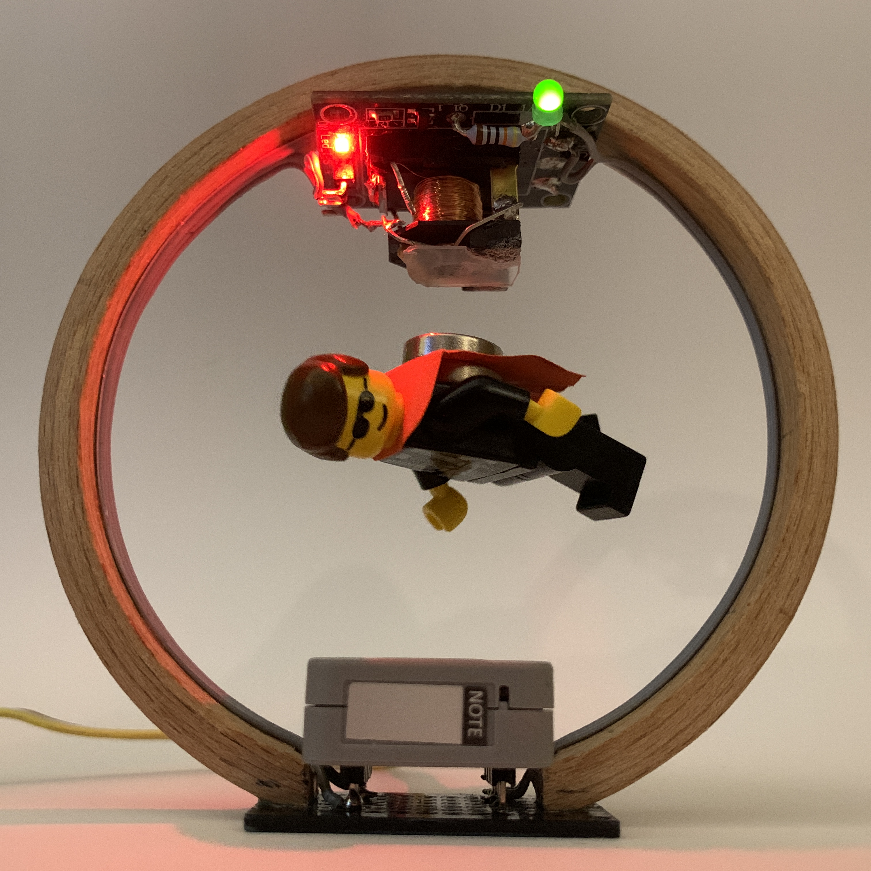
Magnetic-Levitation-Object that needs only …
- an ESP32Pico M5Stack „ATOM LITE“ or „ATOM MATRIX“
- a modified simple 5V-relais and
- a HALL-sensor A1302/A1308.
- The wooden carrier is made of an embroidery frame.
After I had successfully built up a “Magnetic Levitation Object” in conventional analog design and described that in article “Magnetic Levitation – The Easy Way” , I now wanted to replace the technology of the 1980s with modern digital components. The object should also get a little smaller, and -as I hope – more beautiful.
In this video you can see the result: Magnetic Levitation – The Digital Way
Instead of the analog comparator, an ESP32 SoC module from M5Stack is used now. The ATOM LITE or also the ATOM MATRIX are extremely small (24mm*24mm*10mm or 15mm) but still offer all the appreciated features of the ESP32.
So especially a quite fast 12Bit-ADC is available.
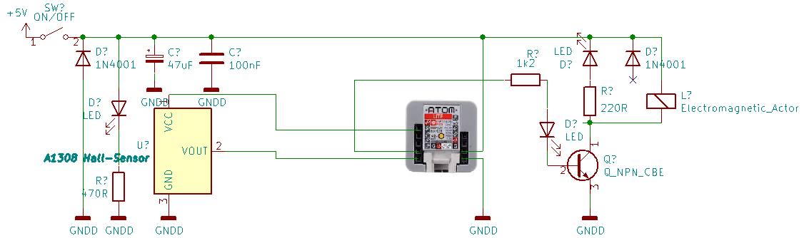
The Hall sensor A1302 is now operated with 3V3 (comming from the internal 3V3-regulator of the ATOM-module) so that the HALL sensor output level is 0V to max. 3V3 and thus suitable for the ESP32 ADC. The 3V3-Vcc is a bit below the data sheet specification of the sensor A130X, but works very well.
Furthermore a modified 5V relay is used as electromagnet – so no winding of coils etc is necessary and the result is predictable and reproducible. The modification of the relay is described in detail HERE. It can be controlled directly with 3V3 from the ESP32-output. As the former relay coil is now switched on/off very fast and has a high inductance, it is important to replace the diode D1 ( parallel to the coil) by an LED with a serial resistor. This limits the flyback voltage/current and preserves T1 against the resulting very high induction voltage. But especially the new LED exactly indicates the level where the electromagnet is very fast switched on and off to keep the payload fly about 15mm below the HALL-sensor.
UPDATE REGARDING THE FLYBACK-DIODE/LED: It has turned out that it is important to keep the flyback current through the LED low, as too high a current keeps the magnetic field for too long, even when the transistor is switched off. This additional field prevents a good control loop and destabilises the flight attitude of the payload. On the other hand, the LEDs and the resistor are absolutely necessary as they limit the induction voltage at the relay transistor to a harmless level of below 50V. TWO WHITE LEDs with a 220 to max. 330Ohm resistor fulfilled this job very well. See https://en.wikipedia.org/wiki/Snubber#Diode_snubbers
The three original connector pins (GND,+,S) are still used to connect the electromagnet.


Attention: The HALL-sensor is now powered with 3V3 at the former “NO”-relais-contact, but the former relais has to be powered with 5V at pin “+”. Both share the same GND at contacts “NC” and “-” ( so I connected them on the board).
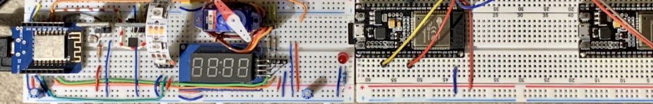
I placed the ATOM LITE at a piece of PCB with 4+5 pins and used two flat band cables at the inner wall of the wooden ring to make the five connections to the board with the electromagnet. M5stack’s ATOM LITE with an ESP32 pico and an USB-C interface is ideal for this, as it is very small and well protected in its housing.


The ATOMs can be powered from USB-C or the grove-port (G and 5V) or via the downside-plugs (G and 5V).
CODE: The small minimalistic ARDUINO IDE program makes sure that the ADC of the ESP32 behaves like the comparator LM311 of the analog version – including the hysteresis, which stabilizes the behavior of the control very much. This is extremely simple to program, but works very well once you have experimentally determined the correct value for the TRIGGER variable. This value is very dependent on the magnets and the payload weight, as there is only a range of a few mm where the electromagnet can control the flightlevel of the magnetic object..
ATTENTION: It turned out that the quality of the 5V supply is very important. At first I had problems with the stability of the flight altitude as long as I used the 5V of my notebook via the USB port. This supply was too unstable and unclean. Only when I connected a USB hub with its own power supply in between it worked very well.
With a future extension of the program this value could be determined in the program and stored in the permanent memory of ESP32. This will make it e.g. more easy to change the payload without code-changing/compiling/uploading again.
At fist I wrote the necessary code in MicroPython, but that turned out to be a bit to slow. So here you see my simple program-code for the ARDUINO IDE and an M5Stack’s ATOM LITE:
/**************************************
Magnetic Levitation object:
Lets a LEGO man, glued together with a neobdymium magnet, float under a modified 5V relay
- SoC:            ESP32, very good: M5Stack's ATOM LITE or ATOM MATRIX
- Electromagnet:  Modified 5V-Relais HW-482 with 3V3/5V transistor input
- Sensor:         HALL-sensor A1302 or A1308
***************************************/
// int TRIGGER     = 2740; // Triggerlevel is set to a level where weight of payload is equal to the force between magnet and electromagnet
int TRIGGER     = 2740; // good for payload = 2 Neobdym-Magnets  and a LEGO-Man
int HYST        = 35;   // Hysterese for trigger level

int HALL_PIN    = 33;   // analog Signal from HALL-sensor at GPIO33
int HALL_VAL    = 0;    //
int RELAIS_PIN  = 23;   // GPIO23 to drive the transistor input of the modified 5V-relais  that is used as electromagnet
int X           = 0;    //


void setup(){
  Serial.begin(115200);
  pinMode(RELAIS_PIN, OUTPUT);
  Serial.print("Magnetic Levitation:   START " );
}


void loop(){
  HALL_VAL =analogRead(HALL_PIN);       //read HALL-Sensor with default 0-3.9V input >> 12bit

  if (HALL_VAL < (TRIGGER + X) ){
    digitalWrite(RELAIS_PIN, HIGH);     // lift the payload
    X = HYST;
  }
  else{
    digitalWrite(RELAIS_PIN, LOW);      // drop the payload
    X = 0 - HYST;
  }
// no delay is best
//  delay (1);
}
__________________________________
UPDATE:
The next step was to extend the ARDUINO code:
- The built in button of the ATOM LITE and ATOM MATRIX operates to determine the right value for the variable TRIGGER by decreasing the preset value with each button press and then show the new value via the serial interface.
- NeoPixel-LEDs of the ATOM MATRIX are now used for a limited animation.

So this is the enlarged code for M5Stack’s ATOM LITE and MATRIX:
/**************************************
Magnetic Levitation object:
Lets a LEGO man, glued together with a neobodymium magnet, float under a modified 5V relay
- SoC: ESP32, very good: M5Stack's ATOM LITE or ATOM MATRIX
- Electromagnet: Modified 5V-Relais HW-482 with 3V3/5V transistor input
- Sensor: HALL-sensor A1302 or A1308
- internal button/switch of ATOM to locate the best TRIGGER-value
- internal 5*5-NeoPixel-matrix of ATOM MATRIX for a limited animation
***************************************/

#include <Adafruit_NeoPixel.h>
#ifdef __AVR__
#include <avr/power.h>
#endif
#define PIN 27
#define NUMPIXELS 25

Adafruit_NeoPixel pixels = Adafruit_NeoPixel(NUMPIXELS, PIN, NEO_GRB + NEO_KHZ800);
//Adafruit_NeoPixel pixels(NUMPIXELS, PIN, NEO_GRB + NEO_KHZ800);

// int TRIGGER = 2740; // Triggerlevel is set to a level where weight of payload is equal to the force between magnet and electromagnet
//int TRIGGER = 2740; // ATOM LITE with 2 Neobdym-Magnets and a LEGO-Man
int TRIGGER = 2672; // ATOM MATRIX with 2 Neobdym-Magnets and a LEGO-Man

int HYST = 35; // Hysterese for trigger level

int BUTTON = 39; // PushButton of M5-ATOM
int HALL_PIN = 33; // analog Signal from HALL-sensor at GPIO33
int HALL_VAL = 0; //
int RELAIS_PIN = 23; // GPIO23 to drive the transistor input of the modified 5V-relais that is used as electromagnet
int X = 0; //
int II = 0;
int CNT = 0;

void setup(){
Serial.begin(115200);
pinMode(RELAIS_PIN, OUTPUT);
pinMode(BUTTON, INPUT_PULLUP);
Serial.println("Magnetic Levitation: START " );

pixels.begin();

}
void loop(){
HALL_VAL =analogRead(HALL_PIN); //read HALL-Sensor with default 0-3.9V input >> 12bit

if (HALL_VAL < (TRIGGER + X) ){
digitalWrite(RELAIS_PIN, HIGH); // lift the payload
X = HYST;
}
else{
digitalWrite(RELAIS_PIN, LOW); // drop the payload
X = 0 - HYST;
}
II = ++II;

switch (II) {

case 1000:
if (digitalRead(BUTTON) == 0){
TRIGGER--;
Serial.print("Trigger ist:\t");
Serial.println(TRIGGER );
}
break;
case 33000:
NEO_ANIMATION();
break;

case 99000:
delay(1); //delay disables the interrupts!!!
pixels.show(); // why here?
// Schreibt erst jetzt den neopixel-Puffer,
// wegen flicker-Problem bei ESP32, wenn show() ohne delay DIREKT nach dem setpixelcolor() kommt.
II = 0;
break;
}
// no delay is best
// delay (1);
}

void NEO_ANIMATION(){
// xxxxxxxxxx

CNT = ++CNT;
switch (CNT) {
case 1:
pixels.clear();
pixels.setPixelColor(12, pixels.Color(0, 10, 0));
break;
case 2:
//do something when var equals 2
pixels.clear();
pixels.setPixelColor(6, pixels.Color(0, 10, 0));
pixels.setPixelColor(7, pixels.Color(0, 10, 0));
pixels.setPixelColor(8, pixels.Color(0, 10, 0));
pixels.setPixelColor(11, pixels.Color(0, 10, 0));
pixels.setPixelColor(13, pixels.Color(0, 10, 0));
pixels.setPixelColor(16, pixels.Color(0, 10, 0));
pixels.setPixelColor(17, pixels.Color(0, 10, 0));
pixels.setPixelColor(18, pixels.Color(0, 10, 0));
break;
case 3:
pixels.clear();
pixels.setPixelColor(0, pixels.Color(0, 10, 0));
pixels.setPixelColor(1, pixels.Color(0, 10, 0));
pixels.setPixelColor(2, pixels.Color(0, 10, 0));
pixels.setPixelColor(3, pixels.Color(0, 10, 0));
pixels.setPixelColor(4, pixels.Color(0, 10, 0));
pixels.setPixelColor(5, pixels.Color(0, 10, 0));
pixels.setPixelColor(9, pixels.Color(0, 10, 0));
pixels.setPixelColor(10, pixels.Color(0, 10, 0));
pixels.setPixelColor(14, pixels.Color(0, 10, 0));
pixels.setPixelColor(15, pixels.Color(0, 10, 0));
pixels.setPixelColor(19, pixels.Color(0, 10, 0));
pixels.setPixelColor(20, pixels.Color(0, 10, 0));
pixels.setPixelColor(21, pixels.Color(0, 10, 0));
pixels.setPixelColor(22, pixels.Color(0, 10, 0));
pixels.setPixelColor(23, pixels.Color(0, 10, 0));
pixels.setPixelColor(24, pixels.Color(0, 10, 0));
break;
case 4:
pixels.clear();
pixels.setPixelColor(12, pixels.Color(0, 0, 5));
CNT = 0;
break;
}
//delay(1);
// delay(1) ist bei esp32 vor pixels-show nötig!!
//pixels.show();

}

[…] MAGNETIC LEVITATION – THE DIGITAL WAY […]