
In the two articles “Magnetic Levitation – The Easy Way” and “Magnetic Levitation – The digital Way” I described how to build a circuit that can keep a small object well in levitation. Only readily available components should be needed for both set-ups and the electromagnet should be as simple as possible to produce.
############# The Magnetic Levitation did fascinate me much. You will find all my related posts collected at https://peterneufeld.wordpress.com/category/magnetic-levitation/ #############
In particular, I ended up liking most the “digital” version with an ESP32pico ATOM LITE from M5Stack. This Article describes my efforts of further simplification of the digital version.
The friendly eMail discussion with Luc Lemmens from the ELEKTOR team was very helpful and stimulating. Thank you Luc!
Based on the hardware and software described in the article “Magnetic Levitation – The digital Way” , I have thus developed a modified version that takes into account some knowledge gained in the meantime.
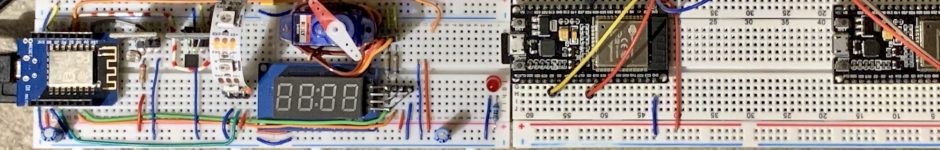
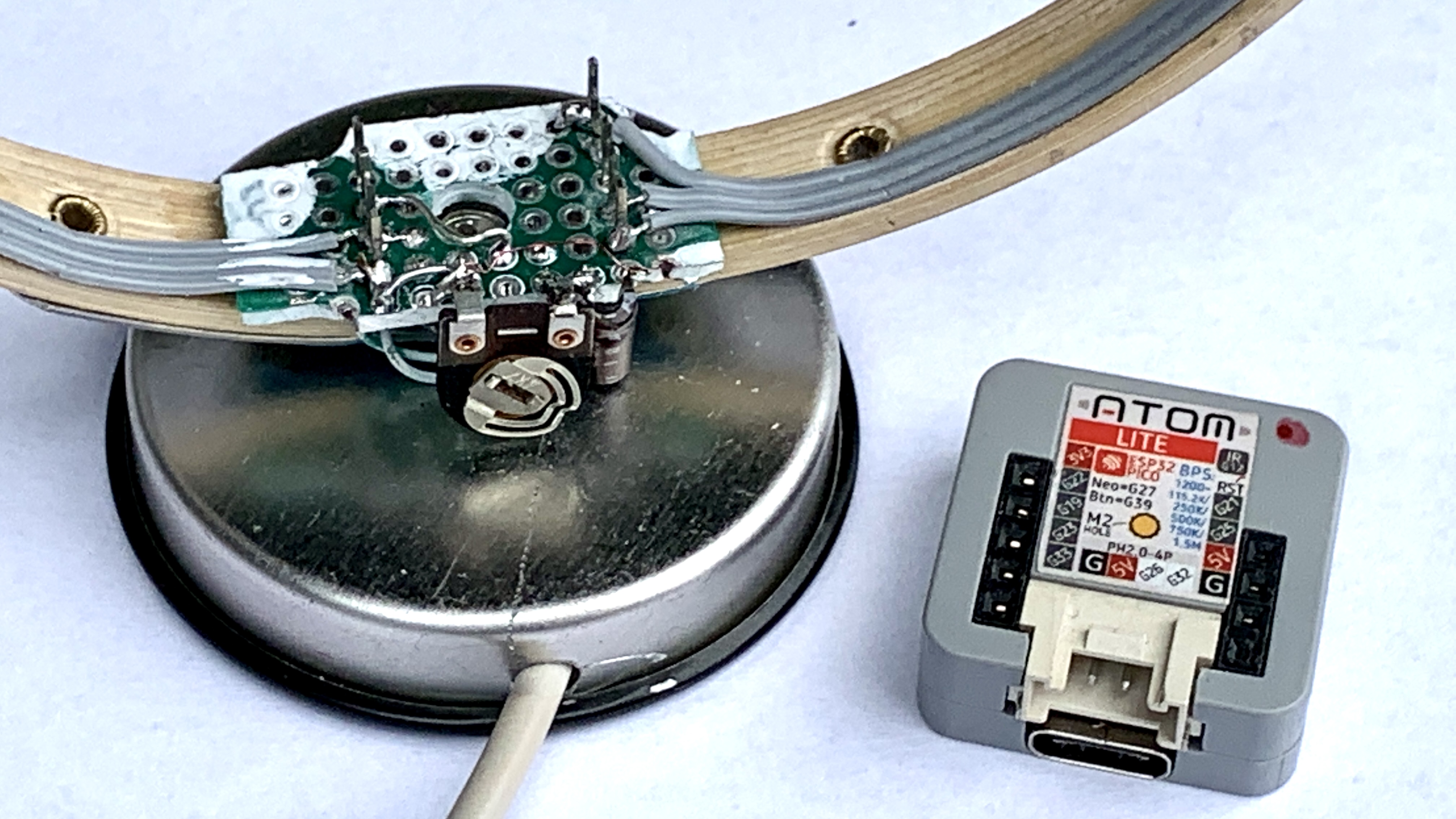
- Although almost any ESP32 board will do the job, I stuck with the ATOM LITE and ATOM MATRIX modules from M5Stack. These are extremely small and well protected in their housings against short circuits caused by vagabond magnets – but they have all the necessary connections to the outside world, making it easy to connect all the hardware you need. The costs remain very moderate.
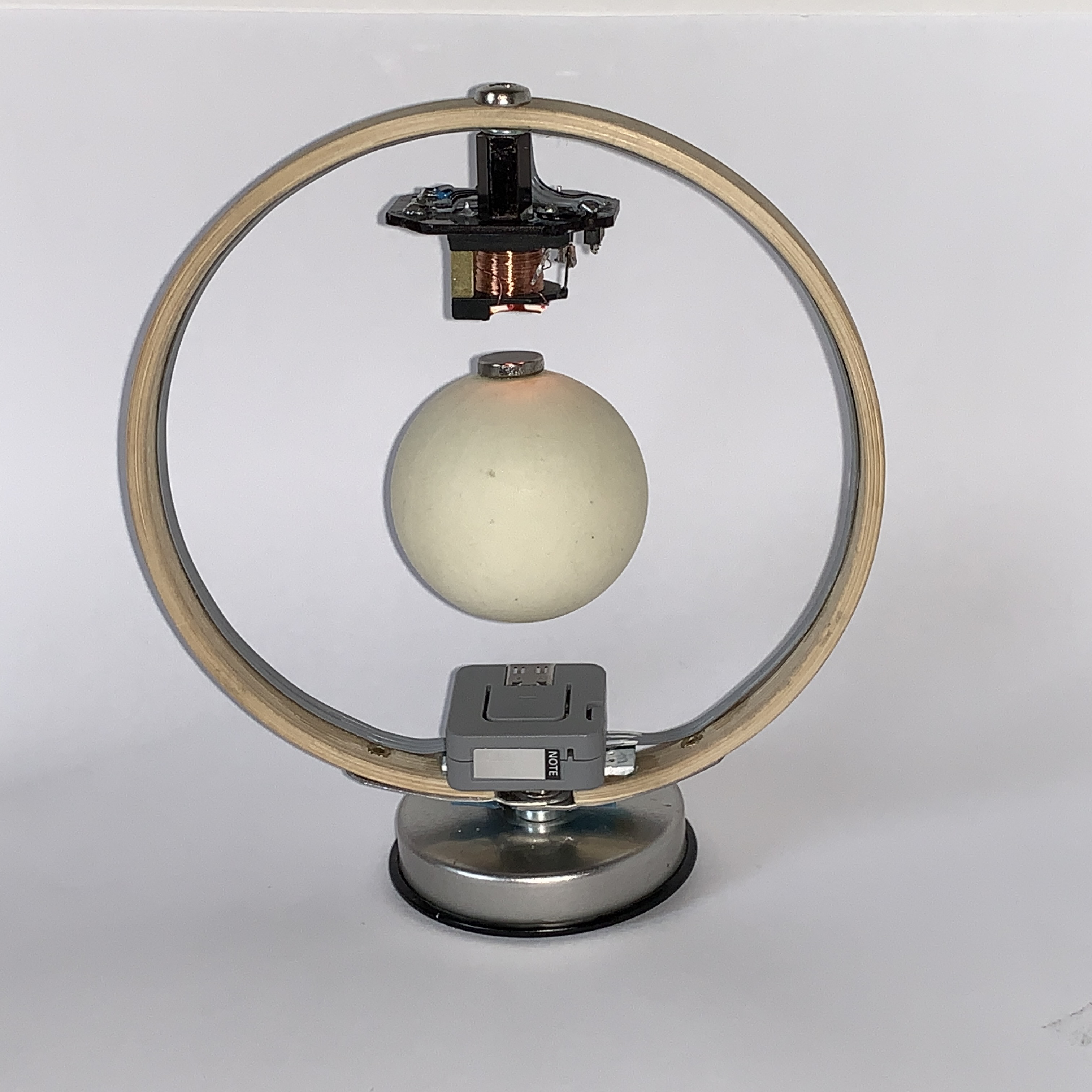
- The support frame is now made from a larger wooden 10cm embroidery frame. This creates space for slightly larger hovering objects.
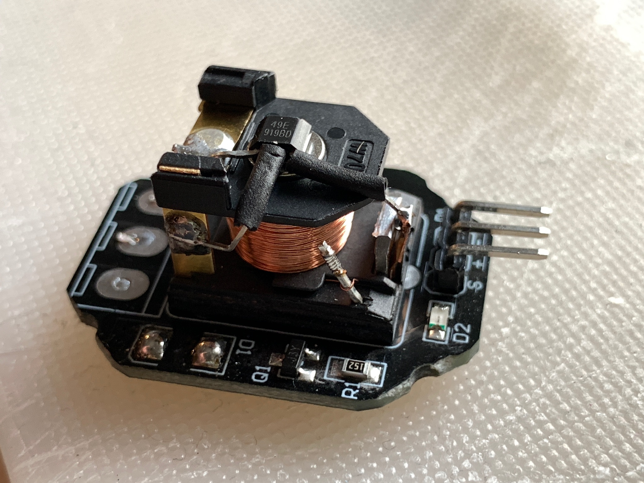
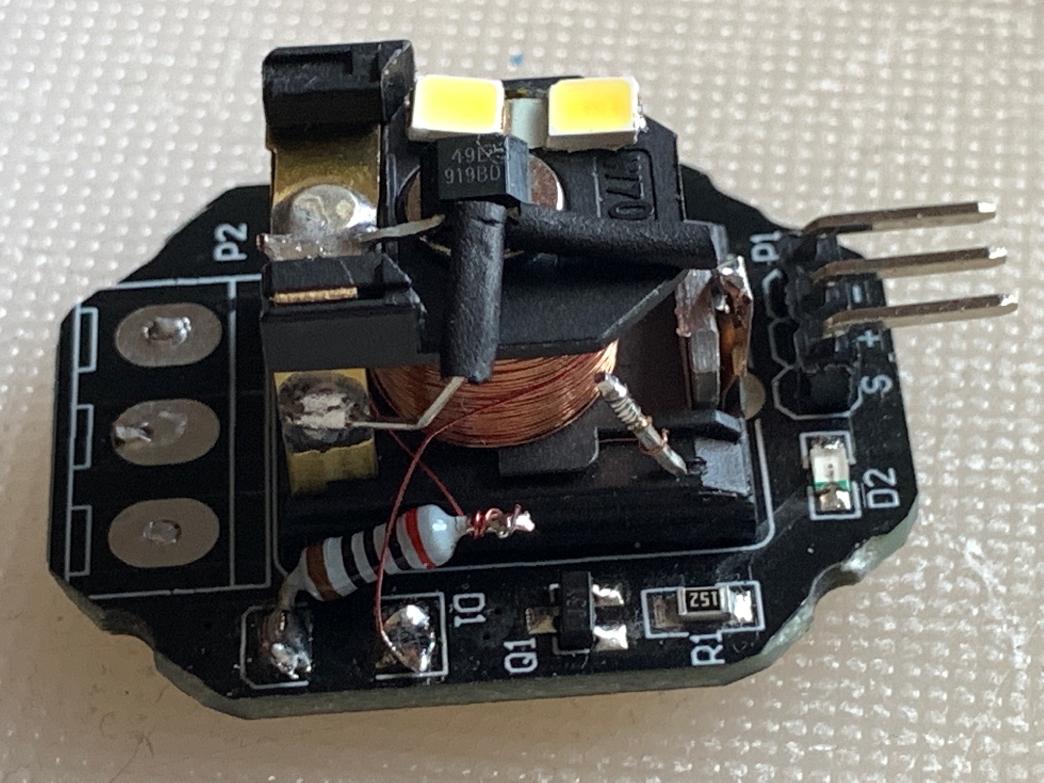
- Relay board / electromagnet: The previous design has proven itself several times. I have now replaced the flyback diode parallel to the relay coil with two white LEDs connected in series and a series resistor. This illuminates the object very nicely from above. These LEDs are also a reliable and good indicator to find the hover zone for a fresh payload. It has turned out that it is important to keep the flyback current through the LED low, as too high a current keeps the magnetic field for too long, even when the transistor is switched off. This additional field prevents a good control loop and destabilizes the flight attitude of the payload. On the other hand, the LEDs and the resistor are absolutely necessary and have to replace the original diode, as they limit the induction voltage at the relay transistor to a harmless level of below 50V and ensure the correct switching pulses. TWO WHITE LEDs with a 220 to max. 330Ohm resistor fulfilled this job very well. See https://en.wikipedia.org/wiki/Snubber#Diode_snubbers
- HALL sensor SS49E: The HALL sensors A1302/A1308 used so far are not readily available and also expensive. The very common and cheap SS49E has now been tested and also works very well. The usual ARDUINO sensor kits very often contain this sensor.
- The supply voltage of the HALL sensor is left at 3V3, as this more stable voltage contributes to better conditions than an often very unstable and unclean 5V supply. And so there is no need to protect the ESP32 from to high input voltage of more than 3V3.
- Setting the trigger threshold for the optimal hover point of different payloads: At first, I pursued the idea of setting the trigger threshold permanently in the code in the software or to record a variable threshold with two UP/DOWN switches and store it in the NVRAM of the ESP32. However, this did not prove to be very practical. Much better was the use of a trimmer known from the analogue version. This allows for easy manual adjustment of the threshold value and “stores” the result in the trimmer hardware: No digital purism but very effective 🙂 The modified circuit therefore contains a small trimmer and uses a second analogue input to record the setpoint for the hovering state.
- A/D converter in the ESP32: The two built-in ESP32 A/D converters are not very linear and seem to produce a lot of noise. In addition, the signal of the HALL sensor is quite unclean. However, the quality of the measurement can be raised a lot by taking the average of several measurements. Two readings distanced by reading out the second channel were sufficient – more did not bring any further advantage and reduced the speed.
- There is some confusion in the Espressif documentation about the voltage range covered by the A/D converter. Since the linearity of the converter is less important here, the entire dynamic range could be used with 12-bit resolution and 11dB attenuation. This allows input voltages up to the level of the 3V3 supply voltage.
- PAYLOADS: Without a magnetic field, the HALL sensors always supply half the operating voltage at their output. With an operating voltage of 3V3 , the output voltage can only be increased by a maximum of about 1.5V. The mentioned sensor types A1302, A1308, SS49E and similar types show at least differences in supply voltage range, magnetic sensitivity (mV/Gauss) and Output Voltage Span. This then influences the maximum detectable strength of a field generated by the magnet in the payload before clipping. In result this limits the possible payloads to light objects and a maximum of two neodymium magnets. Although one magnet is sufficient for a Lego figure, the distance from the coil becomes more favourable when two magnets are used and the object hangs more stably.
The considerations and experiences led to the following, once again simplified, electrical circuitry:

The result now looks like this:
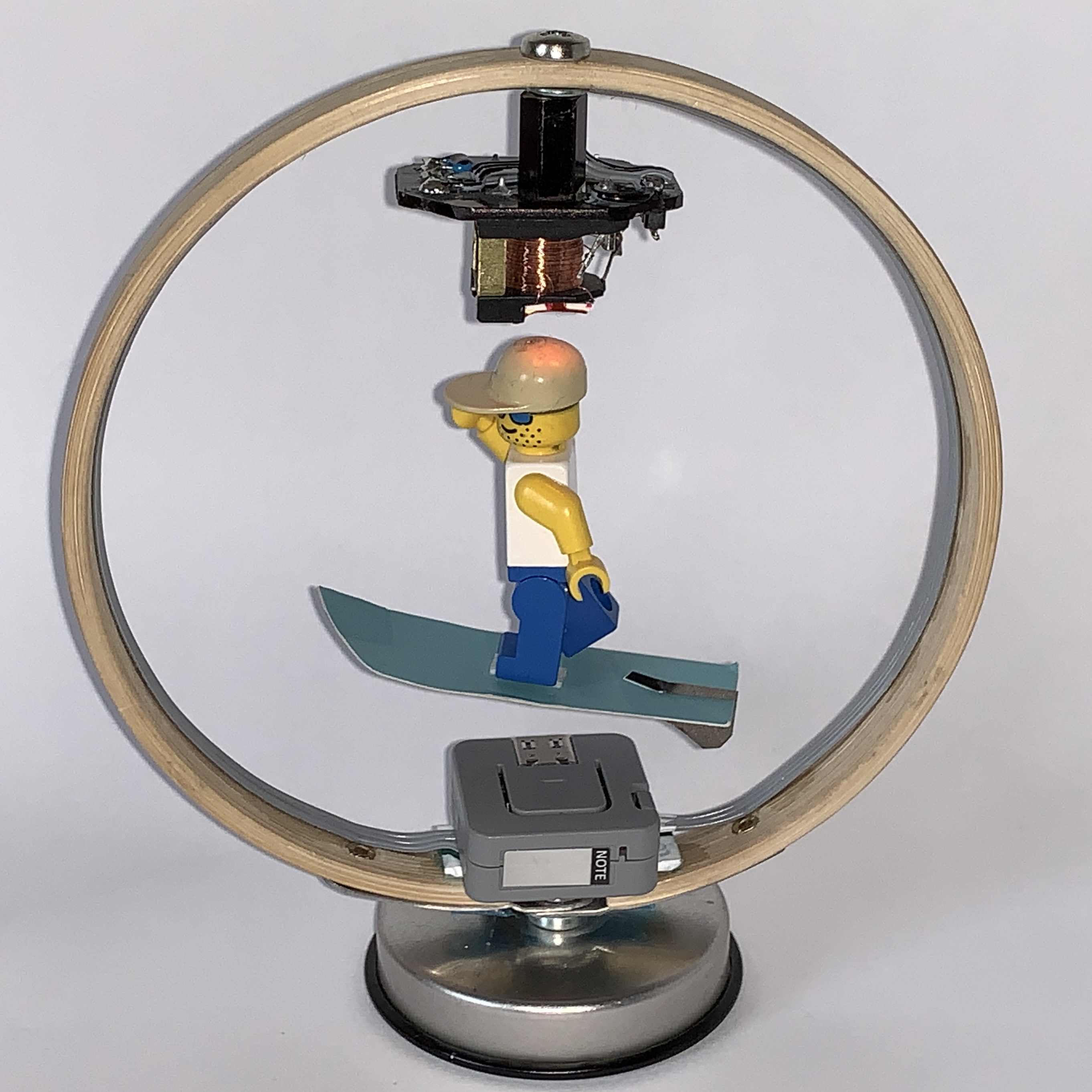
I was able to place the trimmer, resistor and capacitor in the socket in such a way that they are hardly visible from the front when the M5 ATOM is attached. But the trimmer can be adjusted very good with a screwdriver while you hold the payload at the point where you feel the coil begins to attract the payload
It would also be plausible for these components to be placed on top of the relay board. Another line could then carry the setpoint signal from the relay board to the ESP32 socket. However, the chosen solution is mechanically much more stable when adjusting and can also be hidden much better.

The C++ program code got limited to the necessary functions. The set-point can now be acquired with the analogue trimmer through the second ADC_input. The stabilization of the measurements at both analogue inputs gets now improved by multiple measurement. The animation of the NeoPixel in the ATOM LITE or the NeoPixel matrix in the ATOM MATRIX has been omitted here for the time being to simplify matters.
The Arduino Code:
/***********************************************************
 M a g n e t i c   L e v i t a t i o n   c u r c u i t :
     ----- minimal very simple version 3 -------
         Peter.Neufeld@gmx.de 2021/05
      https://peterneufeld.wordpress.com/
A neobdymium magnet with a payload (e.g. a LEGO-man)
floats under an electromagnet made of a modified 5V relay.
 -SoC:          ESP32, good: M5Stack's ATOM LITE or MATRIX
 -Electromagnet:Modified 5V-Relais. Tested: HW-482
 -Sensor:       HALL-sensor.Tested: A1302, A1308 or SS49E
 -Potentiometer:Trimmer to adjust magnets trigger level
HOW TO ADJUST THE CIRCUIT BY THE TRIMMER:
a)Hold payload near the point where it starts to be
  attracted by the core of the electromagnet.
b)Tune trigger level with trimmer until payload hoovers.
c)While tuning observe the flyback LED at electromagnet.
   It indicates the hoover point at which
   the electromagnet turns on/off quickly.
***********************************************************/
int HALL_PIN  = 33;//analog input from HALL-sensor
int HALL_VAL  = 0; //holds output of the HALL-sensor
int ADJ_PIN   = 25;//analog input from trimmer (0 to 2V5)
int ADJ_VAL   = 0; //holds trigger level for actual payload
int HYSTERESIS= 50;//absolute hysteresis for trigger level
int HYST      = 0; //adds or substracts hysteresis
int RELAIS_PIN= 23;//Output to 5V-relay/electromagnet
int i         = 0;
//---------------------------------------------------------
//output to electromagnet
void setup(){pinMode(RELAIS_PIN, OUTPUT);}
// ADCs default is 12bit with 11dB attenuation
//---------------------------------------------------------
void loop(){
  HALL_VAL  = 0;
  ADJ_VAL   = 0;
  for (i=1; i <= 2; i++){    //Read 2 times to avoid noise
   HALL_VAL = (HALL_VAL + analogRead(HALL_PIN));
   ADJ_VAL  = ADJ_VAL   + analogRead (ADJ_PIN);
  }
  HALL_VAL  = HALL_VAL / (i-1);     //compute the average
  ADJ_VAL   = ADJ_VAL  / (i-1);     //compute the average
  ADJ_VAL   = (ADJ_VAL/3)+2450;     //shift to a good range
  if (HALL_VAL < (ADJ_VAL + HYST) ){//Payload too low!
    digitalWrite(RELAIS_PIN, HIGH); //Lift the payload
    HYST = HYSTERESIS;         //Set upper hysteresis level
  }
  else {                            //Payload too high:
    digitalWrite(RELAIS_PIN, LOW);  //Drop the payload
    HYST = 0 - HYSTERESIS;     //Set lower hysteresis level
  }
}
//---------------------------------------------------------


.
.
.
.
.
.
.
.
.
.
.
.
.
.
.
.
.
.
.
.
.
.
.
.
.
. . . . . . . . . . . . . . . .


[…] MAGNETIC LEVITATION – RELOADED […]
Why not use the built-in hall sensor in the Atom ?
That is a good thought at the first look – but it’s hard to find a way to position this built-in sensor ( with unknown characteristics) between load and magnet. Only if you would mount the ESP32 and thus this sensor UNDER the payload there might be a chance to meassure the decreasing magnetic field if the payload-magnet is lifted up. But that would create an object where the payload floats in a very specific small zone just between electromagnet and sensor. I guess the sensor and the magnet then might have only a distance of less then 40mm in this constellation.