
A MAGNETIC LEVITATION project with no special but only standard components – including a modified cheap standard relay as the electromagnet – powered with only 50mA@5V from a USB-Powerbank
A floating object is always a fascinating eye-catcher that I like to put on my desk. Many conversations at this table got off to a nice start thanks to this do-it-yourself object.
So in the last few years I have recreated some “magnetic levitation” projects from various publications.
But I was never really satisfied with the results.: Too big, too unstable, gigantic power consumption(;-), the flight stability was not very good and especially the necessary electromagnet always had to be somehow winded around a screw by myself. The results were often not very nice to look at, but above all only hardly reproducible.
So I had gained a lot of experience over the time and a simple mechanical construction and a simple electrical circuit was created, which proved itself in all test setups:
Here you can see a video of the final setup: https://vimeo.com/430336526
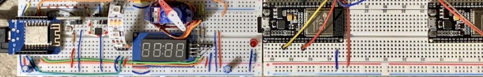
Some Impressions:


The schematic:

Some important results of my experiments:
# The HALL magnetic sensor used is an A1302 or its successor A1308 – the cheaper and widely used SS49 or similar types are NOT suitable. UPDATE: THE HALL-SENSOR SS49E WORKS AS WELL!
# The necessary comparator (not an OP-Amp!) is a LM311
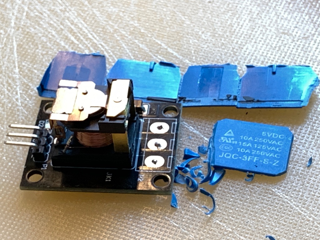
# The magnetic coil is a cheap modified 5V standard relay (tested: HW-482 /JQC-3FF-S-Z or JQC3F-05VDC) with built-in switching transistor from the world of microcontroller actuators. The coil starts anti-clockwise at the PLUS-contact.
# The permanent magnet has to be as strong as possible. At least two but better more stacked NeoDym magnets work best.
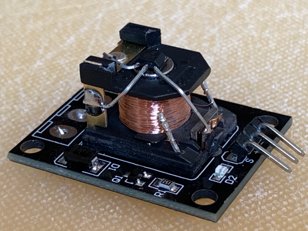
# The non-modified relay has a U-shaped iron core. That core has to be changed to a J-shape by shortening the part that holds the middle-contact of the relay. Thus now only one magnetic pole points towards the “payload”
The next pictures show the steps of modification regarding the relay:
- Remove the screw-contacts on the PCB.
- Carefully remove the relay housing with a cutter starting at the corners.
- Remove the movable middle-contact and shorten the upper static contact.
- Cut off the magnetic counter pole and rest of the movable contact with a Dremel or a metal saw. That modifies the U-shaped core to a J-shaped avoiding the former magnetic shortcut
- Position the Hall sensor with its flat side centered on the coil core.
- Connect the three contacts of the Hall sensor to the rests of the three old relay contacts.
The three relay-contacts are modified to connect the three pins of the A1302/A1308 ( and SS49E) HALL-sensor to the PCB:
- HALL-Vcc-pin1>> relay-NO;
- Hall-GND-pin2>>relay-NC;
- Hall-Vout-pin3>>relay-middle contact


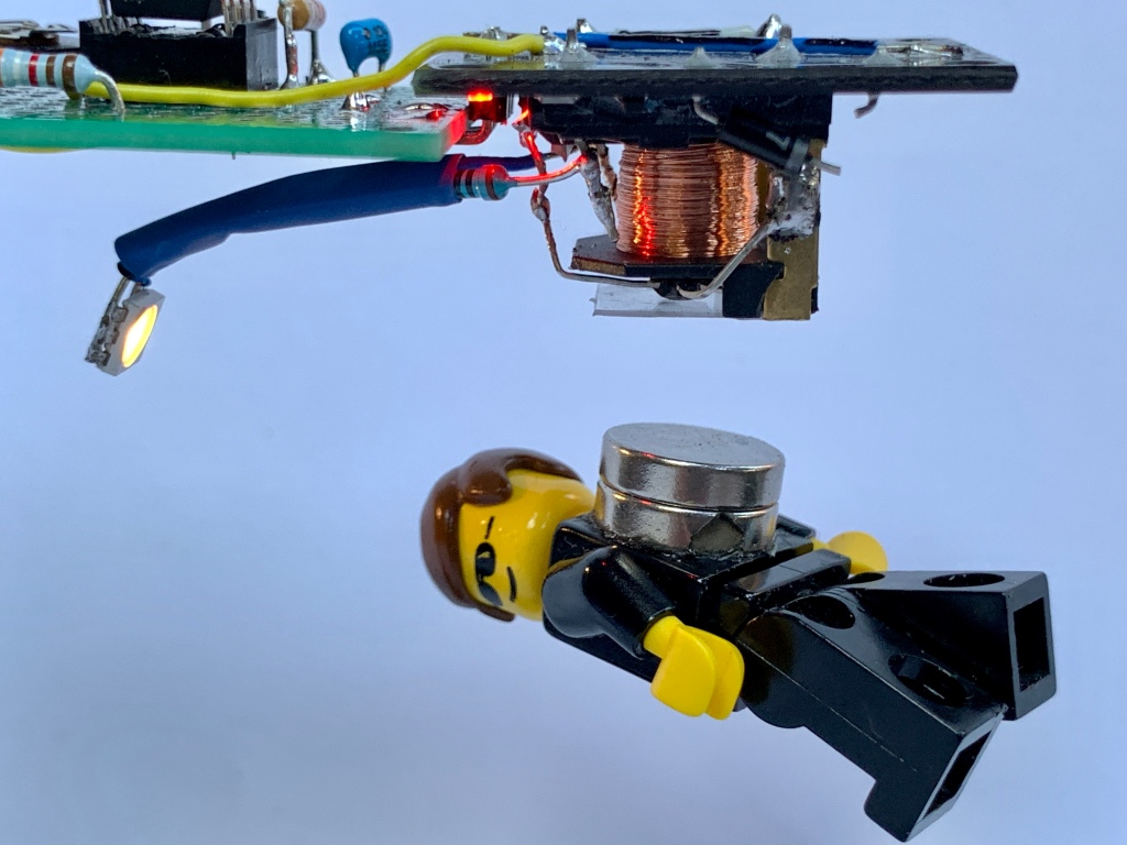
# Two neodymium permanent magnets in disc form with 10mm (or 12mm) diameter and 2mm (or 3mm) height are used to make a LEGO man, a screw or a table tennis ball (with extra payload of a screw) float.
# VOut of the Hall-sensor U1 increases if the magnet comes near – if it decreases turn the magnets around!!!
# The Hall-sensor output rises about 0.2V if the electromagnet is switched on: Else twist the two contacts of the coil!
# The power supply should not get very complicated. In the end it worked very well with only about 50mA at 5V. Thus e.g. a very simple USB power bank can do the power supply for a pretty long time – and can also serve as a safe stand. Attention! Some power banks switch off when the output current is too low! An additional or more current-hungry control LED can remedy this.
# As a positioning aid, the relay’s original flyback diode has been replaced by a white LED with 220R series resistor – this LED only lights up when the object is at the right height and hovers. I found two good positions for this LED: Next to the Hall-sensor (= a bit tricky) or pointing from the side towards the magnets (= easy)
UPDATE REGARDING THE FLYBACK-DIODE/LED: It has turned out that it is important to keep the flyback current through the LED low, as too high a current keeps the magnetic field for too long, even when the transistor is switched off. This additional field prevents a good control loop and destabilises the flight attitude of the payload. On the other hand, the LEDs and the resistor are absolutely necessary as they limit the induction voltage at the relay transistor to a harmless level of below 50V. TWO WHITE LEDs with a 220 to max. 330Ohm resistor fulfilled this job very well. See https://en.wikipedia.org/wiki/Snubber#Diode_snubbers
# An opaque plastic shield protects the HALL-Sensor against shortcut and mechanical stress.
# A PC slot bracket is used to keep the electromagnet at the correct height of about 8cm above the power bank without vibrations. The downside end of the plate gets angled and glued to the power bank with double-sided mounting tape.


Adjusting the autopilot:-)
Important! The payload is mainly carried by the strong permanent magnets at a distance of approx. 15 mm below the core. The weak electromagnet only takes control over a small area of about 2 mm by adding a small electromagnetic force. I’ve got the best results with at least two, better three, strong stacked magnets in the payload.
The fastlane…
I modified three 5V-relays in combination with A1302-Hall sensors. In all setups with a Lego-man and two magnets as payload I had to adjust the potentiometer RV1 for a voltage of 3.45V +-50mV between GND and U1/Pin2 without a near magnet. With SS49E sensor this was 3.95V. Take this as a starting point for the adjustment. The payload is now slowly lifted from below in the direction of the core until you find that it starts to be pulled upwards. The setting of RV1 gets readjusted arround this point. LED D6 gives a feedback for reaching the correct switch point.
Slowly but thoroughly …
The HALL sensor measures the sum of the magnetic field strength of the permanent magnet and the electromagnet. As the magnets approach, the voltage increases at Vout of the HALL sensor. The comparator U1 compares this voltage with the adjustable voltage (RV1) and switches off the electromagnet if the field strength becomes too high.
The permanent magnets including the LEGO man’s load “hang” at the point where their own weight corresponds exactly to the force with which the magnets and the iron core of the coil attract each other. This force is increased somewhat when the electromagnet is switched on. However, as soon as the payload comes too near the Hall sensor measures a magnetic field that is too strong, the electromagnet is switched off and the object “falls” briefly until the Hall sensor again measures a magnetic field that is too weak and the electromagnet lifts the object again. There is a hysteresis created by R3, which influences the created minimal puls width and stabilizes the flight behavior a lot.
At this floating point the electromagnet switches at about 400 times per second. The induction voltage generated when the electromagnet is switched off is no more limited by the build in flyback-diode, but now it causes LED D6 to light up precisely and only at the hover point.
For a basic adjustment at first the hover point must be found. To do this, place a 20mm stack of small Post-It sheets between the magnets and the coil core while the circuit is not powered. The number of sheets is now lowered until close to the point where the magnet just begins to be lifted up only a little bit while the stack of paper is in between.
Hold the magnet at this position and switch the circuit on. Adjust RV1 so that there is a voltage of 0 mV between pin2 and pin3 of U1 and LED D2 just gets dark.
Now the payload is carefully brought to this point without a stack of paper. RV1 only needs to be corrected a little until the object “hangs” safely. D6 now lights up because the solenoid turns on and off quickly.
This procedure of calibration is a bit tricky and depends strong on the weight of the “payload” but especially on the given strength of the strong permanent magnets. Don’t give up!!
I had a lot of fun with this and hope this description will make it easy to build such a “levitation project”.
Good luck!

PS: This was my first post about magnetic levitation. But the story goes on. Please take a look at my meanwhile created posts …
MAGNETIC LEVITATION – THE DIGITAL WAY
MAGNETIC LEVITATION – DIGITALLY RELOADED
MAGNETIC LEVITATION – THE VERY EASY WAY
MAGNETIC LEVITATION – Collection of all my post about it
#
#
#
#
#
#
#
#
#
#
#
#
#
#
#
#
#
#
#
#
#

[…] wrote <here> and at Elektor Labs about my experiments with my magnetic levitation circuits.In the helpful […]
HI,
I am attempting to construct this project (the easy way) but there appears to be a discrepancy between the photo of the constructed board and the schematic.
in the photo there appears to be two electrolytic caps, but the schematic only shows one (1a 47uF) and no 100nf .Can you please help?
Thanks
Jim
Hi Jim, you are right with the discrepancy. I used two 22uF in parallel and the 100nF capacitor is mounted a bit hidden on the downside of the relay board. The values are very uncritical, and the purpose is to keep the supply voltage as clean as possible.
Good luck!
Peter